English
 中文简体
中文简体
Content
- 1 How Photoelectric Water Meters Work: Core Technology Explained
- 2 Key Advantages of Photoelectric Direct Reading Technology for Water Utilities
- 3 Functional Components of a Photoelectric Water Meter
- 4 Vertical Photoelectric Water Meter: Structural Design and Installation Benefits
- 5 Photoelectric Valve Controlled Water Meter: Remote Control and Prepayment Applications
- 6 Communication Protocols: RS485 and M-Bus in Smart Water Metering Networks
- 7 Photoelectric Direct Reading Meters Compared with Traditional Mechanical Metering
- 8 Comparing Photoelectric Water Meter Variants: Feature Overview
- 9 Power Consumption Behavior in Photoelectric Metering Systems
- 10 Applications Across Municipal, Industrial, and Residential Water Management
- 11 Selecting a Photoelectric Water Meter Supplier: Guidance for Manufacturers and Distributors
- 12 About Ningbo Shidai Instrument Co., Ltd
- 13 Frequently Asked Questions
How Photoelectric Water Meters Work: Core Technology Explained
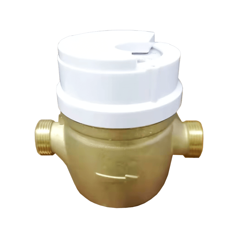
A photoelectric water meter measures water flow mechanically and then reads that measurement using a non contact optical sensor, converting the result into a digital signal that can be displayed locally or transmitted to a remote host system. This is the short answer, and the sections below explain how the technology is built, why utilities and property managers choose it, and how the different product configurations compare. Unlike meters that rely on exposed magnetic coupling to transfer a reading, a photoelectric direct reading water meter isolates the counting register inside a sealed, dry chamber, which keeps the digits legible over a long service life. The optical sensor, typically an infrared emitter paired with a photodiode receiver, reads a coded disc or roller that turns in proportion to the water passing through the meter body. Because the sensor only needs to activate briefly when a reading is requested, the overall design supports low power consumption, which is one of the reasons this technology has become common in battery powered remote reading systems.
Water meters in general, including photoelectric variants, are commonly evaluated against accuracy classes and testing methods described in international references such as ISO 4064 and OIML R49, which define how flow rate ranges and permissible error margins are assessed for cold and hot water meters. A photoelectric water meter can be built with a copper shell, an iron shell, or a stainless steel body shell depending on the installation environment and the water quality conditions it will face. The passive direct reading approach means the meter does not depend on continuous power to maintain an accurate count, since the mechanical register keeps turning regardless of whether the optical sensor is active. When a reading is triggered, either locally or through a request from a remote concentrator, the sensor captures the current position of the coded element and outputs it as a digital value over a communication bus such as RS485 or M-Bus. This structure allows a single photoelectric water meter to serve both as a standalone visual meter and as a node in a larger automatic meter reading network.
Key Advantages of Photoelectric Direct Reading Technology for Water Utilities
Water utilities, property developers, and industrial facility managers generally look at a handful of practical factors when evaluating metering technology, and photoelectric direct reading water meters address most of them directly. Below is a summary of the advantages most frequently cited in technical discussions of this meter category.
- The dry type register structure keeps the digital display window separated from the water flow path, which helps the numbers stay readable over years of service rather than fogging over.
- Non contact optical sensing avoids the wear associated with mechanical contact based reading mechanisms, since the sensor never physically touches the rotating coded element.
- Low power design means the sensor draws current mainly during a reading event rather than continuously, which extends battery life in remote reading configurations.
- Support for RS485 bus or M-Bus data signal output allows the meter to integrate with a host computer system for centralized, automatic meter reading.
- Because the reading mechanism is optical rather than magnetic, the meter is less exposed to interference methods that specifically target magnetically coupled registers.
- Housing options in copper, iron, or stainless steel allow the meter to be matched to the corrosion resistance and mechanical strength requirements of a given installation site.
These characteristics are the reason photoelectric water meter technology is frequently specified in large scale municipal water metering rollouts, in commercial buildings with centralized billing needs, and in industrial sites where remote monitoring reduces the need for manual site visits.
Functional Components of a Photoelectric Water Meter
Before looking at the internal layout of a typical photoelectric water meter, it helps to understand that the device is really a combination of several distinct subsystems working together. Each subsystem has a specific job, and the balance between them determines the overall size, cost structure, and durability of the finished product. The chart below presents an illustrative breakdown of how the internal volume and functional emphasis of a typical photoelectric water meter is generally distributed across its main components. This is a conceptual representation intended to aid understanding rather than a precise measured specification for any single unit. Reading it alongside the explanation that follows should give a clear picture of how the parts relate to one another.
The largest functional share in this illustration belongs to the sensor and encoder module, which reflects the central role that optical reading plays in this meter category. The mechanical counting register follows closely behind, since it is the physical mechanism that actually accumulates the volume of water passing through the body. The communication transmission unit, which handles RS485 or M-Bus signal output, occupies a meaningful share because integration with a host computer system is a core design goal rather than an optional add on. The protective housing and shell, available in copper, iron, or stainless steel depending on the model, accounts for a smaller but still important share, since it directly affects durability in different installation environments. The power module occupies the smallest share, which is consistent with the low power consumption design philosophy behind photoelectric direct reading technology. Because the sensor is only active during a reading event, the power module does not need to be oversized relative to the rest of the meter. This balance between components is one reason photoelectric water meters can maintain a compact body while still supporting remote meter reading functionality. Manufacturers adjust the relative emphasis on these components depending on whether a given model is intended for basic direct reading, vertical installation, or valve controlled operation. Wholesale buyers and system integrators evaluating a photoelectric water meter for a specific project should consider how these functional priorities align with their own network requirements. Understanding this internal structure also helps explain why the dry type register and non contact sensor combination has become a standard reference point across the wider category of photoelectric direct reading water meters.
Vertical Photoelectric Water Meter: Structural Design and Installation Benefits
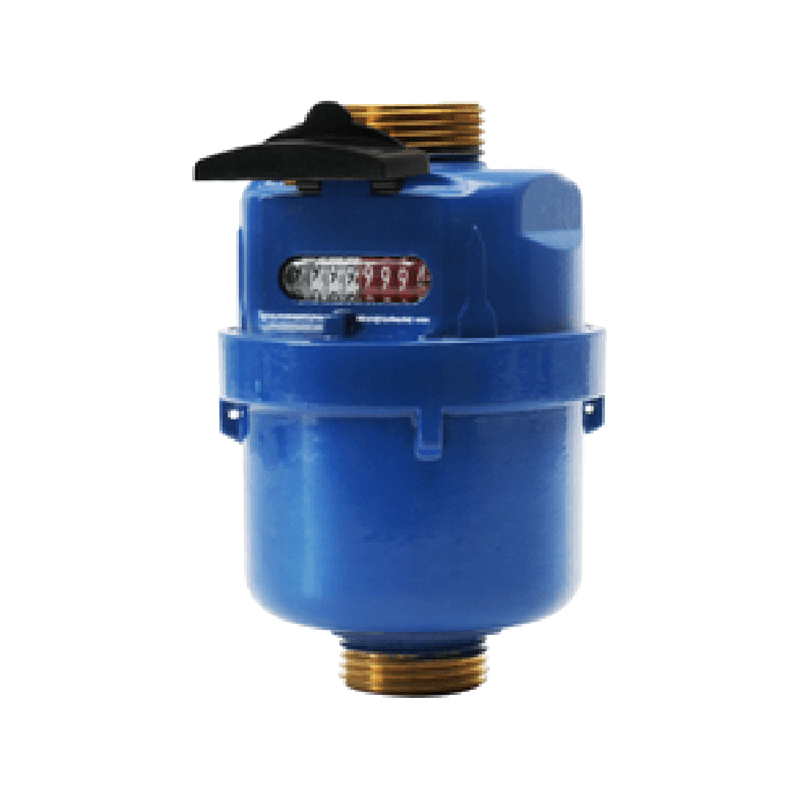
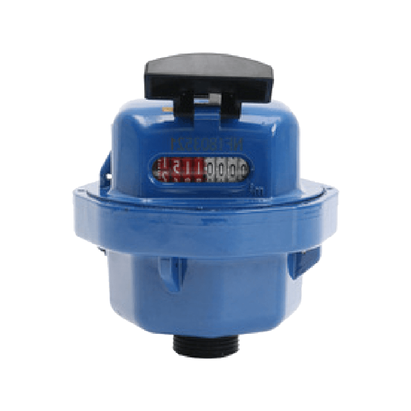
A vertical photoelectric water meter uses the same core reading principle as a standard photoelectric water meter, but its body is designed specifically for installation on vertical pipe runs rather than horizontal ones. This orientation is common in high rise residential buildings, basement pump rooms, and mechanical risers where horizontal installation space is limited. The internal optical sensor and dry type register are arranged so that accuracy is maintained regardless of the vertical mounting angle, which is an important engineering consideration since gravity affects flow behavior differently in vertical piping. Like the standard model, a vertical photoelectric water meter can be produced with a copper shell, an iron shell, or a stainless steel body shell, allowing the housing choice to match the corrosion resistance needs of the installation site.
Because vertical risers are frequently found in multi story buildings with centralized metering rooms, a vertical photoelectric water meter is often paired with RS485 bus or M-Bus based data output so that dozens or hundreds of individual units in a single building can report to one host computer system. This supports large scale remote meter reading without requiring building staff to check each meter in person. The non contact sensor design also means that maintenance staff do not need to worry about mechanical wear from repeated physical contact during readings, which is particularly useful in buildings where meters are read frequently for billing accuracy. For property managers and utility engineers planning vertical pipe installations, this meter type offers a practical way to combine space efficient mounting with the accuracy and remote reading benefits associated with photoelectric direct reading technology.
Photoelectric Valve Controlled Water Meter: Remote Control and Prepayment Applications
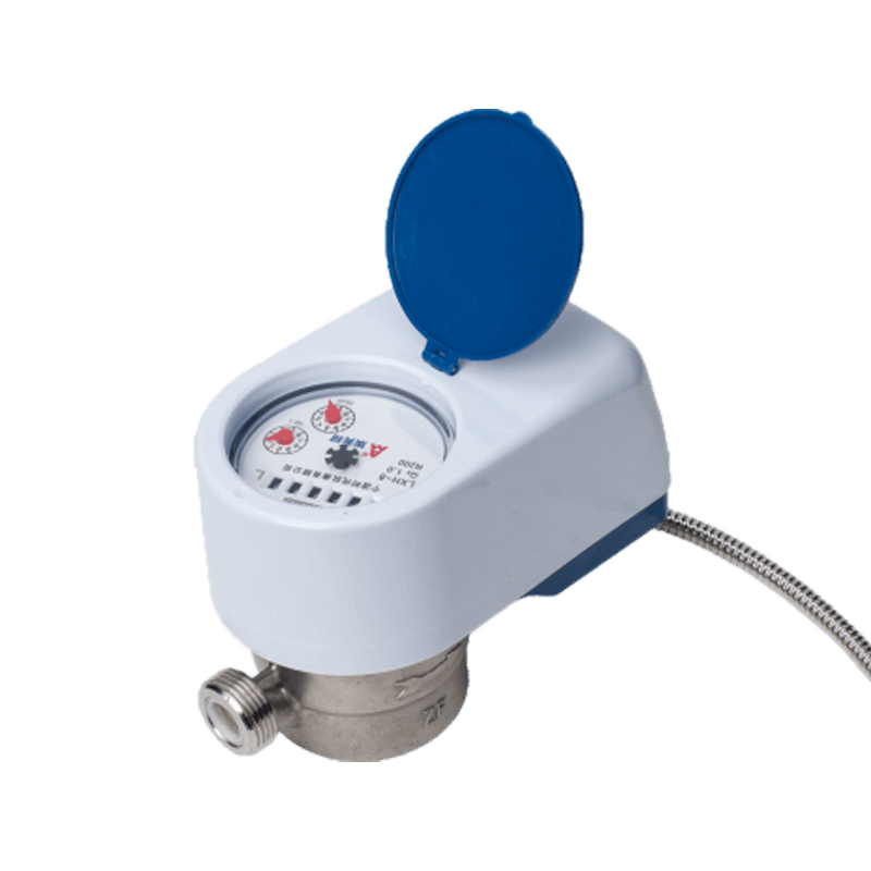
A photoelectric valve controlled water meter combines the standard photoelectric direct reading technology with an integrated valve mechanism, allowing water flow to be opened or closed remotely rather than requiring a technician to visit the site. This design adopts the same photoelectric coding passive direct reading approach used across the broader product family, meaning the dry type register and non contact sensor remain the foundation of the reading system. The added valve function is typically used in scenarios where administrators need to manage water supply status without physical access, such as prepaid water service management, non payment handling procedures, or coordinated shutoff during maintenance work.
Because this meter type still relies on RS485 bus or M-Bus data signal output, valve commands and meter readings can both be handled through the same communication channel connecting to a host computer system. This allows a photoelectric valve controlled water meter to function as part of a broader intelligent water meter reading system, where consumption data and valve status are managed together rather than through separate infrastructure. The low power consumption design is particularly relevant here, since the valve mechanism itself is engineered to operate only when a command is issued, rather than drawing continuous current. For water utilities and property developers considering prepayment or remote administration models, this meter category offers a way to centralize both measurement and control functions within a single device.
Communication Protocols: RS485 and M-Bus in Smart Water Metering Networks
Two communication standards appear consistently across the photoelectric water meter product family, RS485 and M-Bus, and understanding the difference between them helps when planning a metering network. RS485 is a widely used industrial serial communication standard known for differential signaling, which gives it strong resistance to electrical noise over relatively long cable runs, making it a practical choice for connecting many meters back to a single host computer in a building or industrial site. M-Bus, standardized under references such as EN 13757, was developed specifically for utility metering applications, including water, heat, and gas meters, and is widely used across meter reading systems in many regions.
Both protocols allow a photoelectric water meter, whether in standard, vertical, or valve controlled configuration, to output a digital reading that a host system can poll on a schedule or on demand. This bus based structure is what makes automatic meter reading practical at scale, since a single concentrator or data collection unit can communicate with a large number of meters over shared or point to point wiring rather than requiring individual manual visits. System integrators typically choose between RS485 and M-Bus based on existing infrastructure, regional standards, and the software platform used by the host computer system managing the network. Because photoelectric water meters are designed to support either output depending on the model configuration, buyers evaluating suppliers should confirm which protocol matches their planned network architecture before finalizing a specification.
Photoelectric Direct Reading Meters Compared with Traditional Mechanical Metering
It is useful to place photoelectric direct reading technology in context by comparing it, at a general technology category level, with traditional mechanical water meters that rely on magnetically coupled registers rather than optical sensing. This comparison is not about any specific brand but about the underlying design approach used across the wider metering industry. The chart below presents an illustrative, qualitative comparison across four practical dimensions that matter to utilities and facility managers. The ratings are conceptual scores intended to highlight general technology differences rather than precise laboratory measurements. Reading this chart alongside the explanation that follows should clarify why photoelectric direct reading has become a preferred approach in many remote metering projects.
Across all four dimensions shown, the photoelectric direct reading category scores higher in this illustrative comparison, which reflects real structural differences rather than an arbitrary preference. Reading clarity longevity favors photoelectric designs because the dry type register keeps the display window sealed away from water vapor, which helps prevent the fogging that can affect some mechanically coupled registers over time. Magnetic interference resistance is stronger for photoelectric designs because the reading mechanism does not depend on an externally accessible magnetic coupling point, which some traditional meters use to transfer rotation to the register. Remote data output capability shows the largest gap in this comparison, since photoelectric meters are built from the outset to support RS485 bus or M-Bus signal output, while many traditional mechanical meters were originally designed as purely visual, non connected devices. Maintenance efficiency also favors the photoelectric category, partly because non contact sensing reduces the physical wear associated with repeated mechanical reading actions. None of this means traditional mechanical metering lacks a role, since simple visual only applications with no remote reading requirement may not need the added communication capability at all. However, for utilities and property developments planning any form of automatic meter reading or intelligent water meter reading system, the practical advantages of photoelectric direct reading technology become more significant. This is one of the reasons the photoelectric water meter category has expanded across municipal, commercial, and industrial metering projects in recent years. Buyers comparing options should weigh these general category differences against their specific project requirements, including budget structure for the wider network and the communication protocol already in use at their site.
Comparing Photoelectric Water Meter Variants: Feature Overview
The photoelectric water meter product family includes three main configurations, the standard photoelectric water meter, the vertical photoelectric water meter, and the photoelectric valve controlled water meter. While all three share the same underlying photoelectric coding passive direct reading technology, they are optimized for different installation and operational scenarios. The table below summarizes the key distinguishing features of each configuration.
| Model | Housing Options | Communication Output | Valve Control | Typical Installation |
|---|---|---|---|---|
| Photoelectric Water Meter | Copper, iron, or stainless steel | RS485 or M-Bus | Not included | Horizontal pipe runs |
| Vertical Photoelectric Water Meter | Copper, iron, or stainless steel | RS485 or M-Bus | Not included | Vertical risers and pump rooms |
| Photoelectric Valve Controlled Water Meter | Copper, iron, or stainless steel | RS485 or M-Bus | Integrated remote shutoff | Prepayment and managed supply sites |
To visualize these differences in a way that highlights relative strengths rather than a simple checklist, the radar chart below rates each configuration across five practical attributes on a qualitative scale from one to five. These scores are intended as a design oriented comparison of the three configurations relative to one another, based on their intended use cases, and should be read as a guide to selection rather than a certified test result. The five attributes were chosen because they reflect the considerations most engineers raise when specifying a photoelectric water meter for a project. Reviewing the shape of each polygon shows which configuration is best aligned with a particular installation priority. The written explanation after the chart walks through each attribute in more detail.
The standard photoelectric water meter and the vertical photoelectric water meter show very similar profiles across most attributes, which makes sense since they share the same core reading technology and communication options. The main difference between them appears in installation flexibility, where the vertical configuration is purpose built for riser and vertical pipe installations while the standard model is intended for horizontal runs. Both of these configurations show limited valve control capability in this comparison, since neither includes an integrated shutoff mechanism as standard. The photoelectric valve controlled water meter shows a noticeably different profile, with stronger scores in remote reading capability, valve control, and signal output range, reflecting its design purpose around remote administration and prepayment style management. Its installation flexibility score is comparatively lower in this illustration, since the added valve mechanism can introduce additional installation considerations compared to a simpler direct reading unit. Durability scores remain broadly similar across all three configurations, which reflects the fact that housing material choice, whether copper, iron, or stainless steel, is available across the entire product family rather than being tied to a single configuration. This comparison is intended to help buyers match a configuration to their operational priorities, whether that means straightforward horizontal metering, space efficient vertical installation, or centralized remote control of water supply. System integrators planning a mixed network sometimes deploy more than one configuration across a single site, using standard or vertical models for general metering and valve controlled models specifically where remote shutoff is operationally necessary. Because all three configurations share the same RS485 or M-Bus communication foundation, they can typically be integrated into the same host computer system without requiring separate reading infrastructure. This shared foundation is one of the practical benefits of standardizing on a single photoelectric water meter product family across a large scale project rather than mixing unrelated metering technologies.
Power Consumption Behavior in Photoelectric Metering Systems
Low power consumption is one of the defining design goals of photoelectric direct reading technology, and understanding why requires looking at when the meter actually draws current rather than just how much it draws in total. The chart below illustrates the general pattern of power draw over a typical operating cycle, contrasting a low, mostly flat baseline with short spikes that occur only during active reading events. This is a conceptual, schematic illustration rather than a measured power log from a specific unit, intended to demonstrate the event triggered design principle rather than exact values. The pattern shown is representative of how photoelectric sensors are commonly designed to behave in battery supported remote reading applications. The explanation following the chart discusses why this behavior matters for long term deployment.
The dominant feature of this pattern is the long, flat baseline period, during which the photoelectric sensor remains largely inactive because no reading is being requested from the meter. During these baseline periods, the mechanical register continues to accumulate the water volume passing through the meter body without requiring any electrical power at all, since the counting mechanism is purely mechanical. Power is only required when the host system or a local request triggers a reading, at which point the optical sensor briefly activates to capture the current position of the coded element. This event triggered behavior is fundamentally different from continuously powered digital sensing approaches, where the sensor or processor may need to remain active or poll at frequent fixed intervals regardless of whether a reading is actually needed. By concentrating power draw into short, infrequent spikes, a photoelectric water meter can be paired with a modest battery or power module while still supporting years of operation in the field. This is particularly important in remote installations where physical access for battery replacement is inconvenient or costly to arrange, such as underground vaults, high rise risers, or large scale utility deployments spanning many individual meters. The RS485 or M-Bus communication interface itself is also generally designed with power efficiency in mind, since a network with many meters needs each individual device to contribute a proportionally small load to the overall system. Understanding this power behavior also helps explain some of the guidance given to installers, such as recommendations around signal cabling and communication scheduling, since less frequent polling generally reduces cumulative power draw across the network. For utilities and integrators planning a large scale automatic meter reading rollout, this event triggered power design is one of the practical factors that supports long term reliability without requiring frequent field maintenance. It is also a key reason photoelectric direct reading technology is frequently selected over continuously powered alternatives in projects where minimizing ongoing maintenance visits is a priority.
Applications Across Municipal, Industrial, and Residential Water Management
Photoelectric water meters, in their standard, vertical, and valve controlled configurations, are used across a range of settings where accurate measurement and remote data access are both important. Municipal water utilities frequently use this technology to support large scale automatic meter reading programs, reducing the need for door to door manual readings across thousands of connections. Commercial and residential property developments use vertical photoelectric water meters in centralized riser rooms, allowing building management to monitor consumption across many units from a single host computer system. Industrial facilities often value the non contact sensor design and RS485 or M-Bus output for integrating water consumption data into broader facility monitoring and resource management systems. Prepayment water service programs, particularly in regions where remote administration of supply status is operationally useful, often rely on the photoelectric valve controlled water meter to combine measurement and control in a single device. Across all of these applications, the underlying photoelectric coding passive direct reading technology provides a consistent foundation, meaning operators can standardize on familiar communication protocols and reading procedures even as they deploy different configurations for different parts of a project.
Selecting a Photoelectric Water Meter Supplier: Guidance for Manufacturers and Distributors
Manufacturers, system integrators, and wholesale distributors evaluating a photoelectric water meter supplier typically look beyond the basic specification sheet to assess how well a product will perform across a large scale deployment. Below is a short list of practical considerations often raised during supplier evaluation.
- Confirm which communication protocol, RS485 or M-Bus, matches the host computer system and network architecture already in use or planned for the project.
- Review the available housing material options, including copper, iron, and stainless steel, against the water quality and installation environment at the target site.
- Determine whether the project requires standard direct reading units, vertical configurations for riser installations, or valve controlled units for remote shutoff and prepayment functionality.
- Ask about production consistency and quality management processes, since large scale rollouts depend on batch to batch uniformity across thousands of individual meters.
- Request technical documentation covering integration procedures for the intelligent water meter reading system, so installation teams can plan network commissioning efficiently.
Manufacturers and wholesale buyers sourcing photoelectric water meters for distribution or large project deployment generally benefit from working with a supplier that can support all three configurations under one product family, since this simplifies technical documentation, training, and long term parts availability across a mixed network.
About Ningbo Shidai Instrument Co., Ltd
Ningbo Shidai Instrument Co., Ltd is a subsidiary of AMICO Group. It is a comprehensive high tech enterprise specializing in the research, development, production, and sales services of AMICO brand IC card water meters, Bluetooth water meters, heat meters, photoelectric direct reading meters, pulse remote transmission meters, LORA wireless meters, NB wireless meters, WS water meters, WPD water meters, single flow communication water meters, capacitive direct drinking water meters, and intelligent water meter reading systems. As part of this broader product portfolio, the company applies photoelectric coding passive direct reading technology across its photoelectric water meter, vertical photoelectric water meter, and photoelectric valve controlled water meter lines, supporting RS485 bus or M-Bus data signal output for integration with host computer based remote meter reading systems.
Frequently Asked Questions
Q1: What does photoelectric direct reading mean in a water meter
It refers to a design where a non contact optical sensor reads a coded mechanical register directly, converting the measurement into a digital signal without relying on a magnetically coupled reading mechanism.
Q2: How does a photoelectric water meter differ from a standard mechanical meter
The main difference is the reading mechanism itself, since a photoelectric meter uses an optical sensor and dry type register rather than a magnetically coupled dial, which supports better long term clarity and remote data output.
Q3: Can photoelectric water meters integrate with existing remote reading systems
Yes, these meters are designed to output data over RS485 bus or M-Bus, which allows them to connect with a host computer system used for automatic meter reading.
Q4: What is the purpose of the valve function in a photoelectric valve controlled water meter
The integrated valve allows water supply to be opened or closed remotely, which supports use cases such as prepayment management and coordinated supply control without a site visit.
Q5: What housing material options are available for photoelectric water meters
The body shell can be produced in copper, iron, or stainless steel, allowing the housing to be matched to the water quality and durability requirements of a given installation.