English
 中文简体

Content
- 1 Clamp-On Ultrasonic Flow Meter: The Short Answer
- 2 How the Measurement Works Without Touching the Water
- 3 Clamp-On Versus Inline: An Honest Comparison
- 4 Accuracy: Reading the Datasheet Properly
- 5 Installation: Where Most Clamp-On Projects Go Wrong
- 6 Where Clamp-On Meters Earn Their Money
- 7 Matching the Measurement Principle to the Job
- 8 A Sourcing Checklist for Procurement and Engineering Teams
- 9 Price, Lead Time and Running Costs
- 10 Choosing a Manufacturer or Supplier
- 11 Frequently Asked Questions
- 11.1 How accurate is a clamp-on ultrasonic flow meter in real service?
- 11.2 Can a clamp-on ultrasonic flow meter be used for billing?
- 11.3 What pipe materials and sizes does clamp-on work on?
- 11.4 Why does the reading drop out at low flow?
- 11.5 Does the meter work on wastewater and slurries?
- 11.6 How much straight run is required?
- 11.7 Can it measure both forward and reverse flow?
- 11.8 What maintenance does a permanent installation need?
- 11.9 Is a clamp-on meter a good substitute for an in-line ultrasonic water meter?
- 12 Related Reading
A district heating crew needs a flow reading on a 200 mm steel header installed in 1998. There is no spare flange, the line cannot be drained before Friday, and the billing team wants numbers. Someone suggests a clamp-on ultrasonic flow meter: two transducers strapped to the outside of the pipe, a length of signal cable, a display in the control room.
The suggestion is usually a good one, with one condition attached. A clamp-on ultrasonic flow meter is chosen for what it avoids, not for being the most precise instrument on the shelf. Feed it accurate pipe data and a clean, single-phase liquid and it will hold within roughly one to two percent of reading. Feed it a scaled pipe interior, entrained air and a guessed wall thickness, and it will still display a confident number that happens to be wrong. The entire job, from quotation to commissioning, is about keeping that number honest.
A clamp-on ultrasonic flow meter is the right instrument when you need flow data from an existing pipe without interrupting service. It is not a substitute for an approved in-line meter on a billing line.
Clamp-On Ultrasonic Flow Meter: The Short Answer
A clamp-on ultrasonic flow meter measures liquid velocity through acoustic signals that travel across the pipe wall and through the fluid. Nothing touches the water. There is no spool piece, no flange gasket, no drilled tapping, and no pressure drop added to the network. The transducers are mounted on the outside surface, spaced at a calculated distance, and coupled to the pipe with grease, gel or a solid pad.
That design makes it the natural choice for four situations: measuring flow in pipework that cannot be shut down, verifying whether an existing large meter is drifting, taking temporary readings for a survey or a dispute, and adding flow data to a system where the original design left no room for a meter body. Fixed-installation versions run continuously and feed a control system; portable versions are carried from site to site with an internal battery and a data logger.
What it does not do well is act as the cash register. In most water utility jurisdictions, billing meters must be type-approved and pattern-tested as a complete assembly, and a transducer pair strapped to a pipe of unknown wall thickness rarely qualifies. Clamp-on instruments are best understood as diagnostic, verification and temporary measurement tools, and as permanent monitoring devices on secondary lines where a small uncertainty is acceptable.
How the Measurement Works Without Touching the Water
Transit-time is the workhorse
The dominant method is transit-time, also called time-of-flight. One transducer fires a pulse diagonally downstream, the other fires diagonally upstream, and the electronics compare the two travel times. Sound moves faster with the flow and slower against it. The difference is tiny, measured in nanoseconds, but it scales with velocity, so the meter converts it into metres per second and then into cubic metres per hour using the pipe's internal cross-section.
Transit-time needs a liquid that carries the signal cleanly. Clean water, treated water, chilled water, glycol mixtures and most light chemicals are ideal. Liquids loaded with suspended solids or bubbles scatter the beam, and very thick or very rough pipe walls weaken it before it even reaches the water.
Doppler is for liquids that carry something
Doppler meters listen for frequency shift from particles or bubbles moving with the flow. They are useful on wastewater, slurries and aerated streams where transit-time struggles, but they need a minimum concentration of reflectors and they generally deliver a wider uncertainty band. Some instruments combine both methods and switch automatically, which is convenient but should not be read as a guarantee of accuracy on every fluid.
What the signal must pass through
Between the transducer and the water there are five layers: the coupling compound, the pipe wall, the internal liner if one exists, the fluid itself, and any deposit sitting on the inner surface. Each one costs signal. A sound path that has to cross 8 mm of steel plus 3 mm of cement lining plus 2 mm of scale is a much harder job than the clean 4 mm stainless line on the test bench, and the meter's stated accuracy assumes reasonable conditions, not worst-case ones.
Clamp-On Versus Inline: An Honest Comparison
Buyers usually narrow the choice to three routes: a clamp-on transducer set, an in-line ultrasonic spool piece with the transducers built into the body, or a mechanical meter such as a Woltman or single-jet type. The comparison below is a practical summary rather than a specification, because models within each category vary widely.
| Consideration | Clamp-on ultrasonic | In-line ultrasonic spool | Mechanical (Woltman or jet) |
|---|---|---|---|
| Installation impact | No cutting, no shutdown, mounted on live pipe | Requires pipe cut-out and isolation | Requires cut-out, strainer and straight runs |
| Pressure drop | None | None | Small but permanent |
| Typical accuracy | About 1% to 2% of reading | About 0.5% to 1% of reading | About 2% of reading in the upper flow range |
| Low-flow performance | Limited, signal fades below roughly 0.2 to 0.3 m/s | Good, with defined cut-off point | Very good at low flows on jet meters |
| Dependence on pipe data | High: wall thickness, liner and material matter | None, the bore is manufactured | Low, the body defines the bore |
| Billing suitability | Rarely type-approved as a revenue meter | Available as an approved meter | Standard for utility billing |
| Best use | Verification, surveys, retrofit monitoring | Permanent accurate measurement | Revenue metering and cost-sensitive networks |
The comparison explains why so many utilities keep both types on the shelf. The clamp-on set travels in the van and answers the question "is this big meter still telling the truth?" The in-line or mechanical unit stays in the ground and produces the bill. Treating one as a replacement for the other is where procurement arguments usually start.
Accuracy: Reading the Datasheet Properly
Three numbers decide whether a quoted accuracy figure is meaningful. First, whether it is expressed as a percentage of reading or a percentage of full scale; on a meter used mostly at 30% of range, the difference can be a factor of three. Second, whether it comes with reference conditions attached, usually a specific pipe material, a specific wall thickness and a fully developed flow profile. Third, whether the vendor publishes repeatability and zero-drift figures separately, because a repeatable instrument that drifts gives consistent errors rather than random ones.
Velocity range matters just as much as the headline accuracy. Most clamp-on instruments have a working band from around 0.3 m/s up to 5 m/s or more, and their best performance sits in the middle of that band. Below the low-flow threshold the signal-to-noise ratio collapses and the reading becomes noise with a decimal point.
The chart below shows the accuracy bands that commonly appear in published specifications for the four technologies most often compared in water and HVAC projects. It is indicative only: individual models will sit above or below these ranges, and site conditions move the real result more than the catalogue does.
Typical stated accuracy, percent of reading
Reading the chart in context changes the conclusion. A clamp-on instrument at ±1.5% of reading is perfectly adequate for balancing a heating circuit or checking whether a bulk meter is over-reading by a tenth, but it is not adequate to defend a five-figure billing dispute. An in-line ultrasonic meter such as the spool-type units in our ultrasonic water meter range is built around a machined bore, so the cross-section is known rather than inferred, and that single fact removes most of the uncertainty that clamp-on installations carry. Mechanical Woltman meters, including the large-diameter horizontal models we manufacture for main-line duty, give excellent service life and cost per unit, and their accuracy at high flow is predictable; their trade-off is pressure loss and wear over years of service.
One more habit worth building: ask for the calibration certificate and the test rig description, not just the accuracy line. A meter calibrated on a 100 mm stainless rig and then installed on a 300 mm cast iron main is working from a reference that no longer matches its reality.
Installation: Where Most Clamp-On Projects Go Wrong
Pipe data you must collect before quoting
Five measurements decide the transducer spacing and the volume calculation: outside diameter, wall thickness, pipe material, liner material and liner thickness. Outside diameter is usually measurable on site. Wall thickness is where projects fail, because the installer guesses 6 mm on a pipe that is actually 8 mm, and the internal area used for the volume calculation is then wrong by several percent before any acoustic issue appears. An ultrasonic thickness gauge costs less than a second site visit.
Material matters because sound speed differs between carbon steel, stainless steel, cast iron, copper, PVC and PE. Liner matters even more. A bonded cement lining can be handled with the right configuration, but a loose liner or a heavily scaled interior will scatter the beam and produce unstable readings that no amount of gain adjustment will fix.
Surface preparation and couplant
The transducers need a clean, smooth, paint-free patch of pipe. Rust, loose paint and mill scale must be removed, and the area should be sanded to a consistent finish. Couplant fills the microscopic gap between transducer and pipe; grease works for temporary work, solid pads or epoxy are used for permanent installations where re-greasing is impractical. Couplant dries out, and a reading that slowly drifts over two years is often a couplant problem rather than an electronics problem.
Straight runs, spacing and mounting pattern
Aim for ten pipe diameters of straight run upstream and five downstream as a working rule, and increase the upstream figure after a double bend, a partly closed valve or a pump discharge. Transducer spacing is calculated by the instrument, but the mounting pattern is a judgement call. The V method, with both transducers on the same side reflecting off the far wall, suits small and medium pipes. The Z method, with transducers opposite each other, gives a stronger signal on large pipes and on lines with heavy wall or liner. The W method adds extra reflections for small bores where the path is short. Whichever pattern is chosen, the two transducers must sit on the same axis and at the same distance from the nearest fitting.
Power, output and integration
Fixed installations need a decision on power: mains, 24 V DC or battery with a multi-year life. Outputs typically include 4–20 mA, pulse, and Modbus or M-Bus for direct reading into a SCADA or AMR system. If the meter is going onto a remote site with no power, battery sizing and reporting interval become the design constraints rather than accuracy.
Where Clamp-On Meters Earn Their Money
In practice, most clamp-on purchases fall into a handful of recurring jobs:
- Bulk meter verification. A portable unit compared against a plant's master meter answers the annual question of drift without breaking the seal on the pipeline.
- District metered area surveys. Temporary installation on a distribution main for a week or two, logging at one-minute intervals, gives a demand profile that no monthly meter reading can show.
- HVAC balancing and energy checks. Chilled water and heating circuits are ideal fluids, and the non-invasive clamp keeps the system closed and pressurised.
- Leak and loss investigation. Comparing inflow and outflow across a zone quickly narrows down where water is disappearing.
- Process monitoring on aggressive or ultra-clean liquids. Where a wetted sensor would corrode, contaminate or need frequent cleaning, external measurement solves a maintenance problem rather than a metrology one.
- Temporary flow data during commissioning. New plant often runs for months before the permanent instrumentation is loop-checked.
When an in-line meter is the better purchase
If the pipe can be isolated, if the measurement will feed a permanent control loop, or if the number will end up on an invoice, the non-invasive advantage stops being worth its uncertainty. A spool-piece meter removes the wall-thickness question entirely, holds a tighter accuracy band and can be supplied as a type-approved unit.
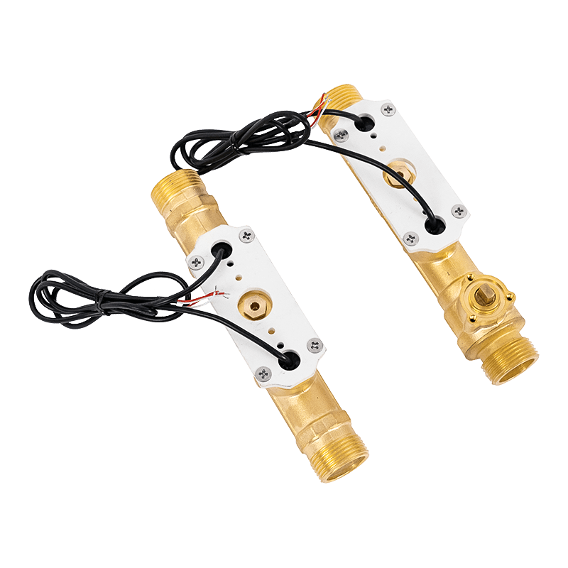 In-Line Ultrasonic Water Meter for Permanent MeteringFor isolated pipes feeding billing or control loops, this in-line ultrasonic meter offers brass or cast-iron bodies, R≥250 metering and remote-reading interfaces.View Product →
For small and medium residential or light commercial lines, an in-line ultrasonic water meter with a machined body and a defined metrological class is a more defensible choice than a clamp-on set that depends on site measurements. It also integrates cleanly with remote reading platforms when the site later moves to automatic data collection.
Matching the Measurement Principle to the Job
Clamp-on ultrasonic is one of three sensible answers to a liquid flow question, and the choice usually comes down to conductivity, pipe size and how much uncertainty the application can absorb.
Electromagnetic meters need a conductive liquid, typically above 5 µS/cm, which covers almost all potable water, raw water and wastewater. They measure across the full bore with no obstruction, hold accuracy well across the flow range, and are unaffected by the velocity profile details that bother ultrasonic transit-time instruments. Their limits are non-conductive liquids, empty-pipe conditions and a cost that scales with diameter.
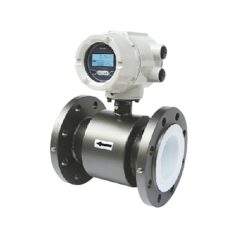 Electromagnetic Water Meter for Bidirectional District MeteringFor conductive water and wastewater, this full-bore electromagnetic meter supports bidirectional DMA metering, high accuracy, IP68 protection and remote data collection.View Product →
Mechanical meters remain the workhorse for revenue metering on distribution networks, particularly at large diameters where a Woltman-type horizontal unit handles high sustained flow with a low cost per unit and a long, well-understood service life. They need a strainer, a straight run and periodic servicing, and they add a small permanent head loss, but their behaviour is predictable and their approvals are mature.
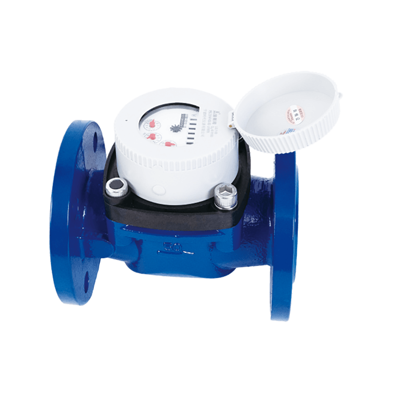 WPD Horizontal Screw-Wing Water Meter for Large FlowA detachable Woltman meter for large-flow mains and billing points, with IP68 register, built-in strainer and optional pulse or wireless output.View Product →
A simple decision order works for most projects. If the pipe cannot be opened, start with clamp-on. If it can be opened and the liquid conducts, look at electromagnetic. If the line is a billing point on a large distribution main, compare a mechanical Woltman against an in-line ultrasonic on total cost over ten years, not on purchase price alone.
A Sourcing Checklist for Procurement and Engineering Teams
Clamp-on meters are frequently bought through distributors and wholesalers who stock a few popular configurations, so the specification work has to happen before the enquiry, not after delivery. The list below covers what a competent manufacturer or supplier will ask, and what a weak quotation will quietly skip.
- Pipe outside diameter, wall thickness, material and liner, with the measurement method stated.
- Fluid type, expected temperature range and pressure, plus whether the line can run dry.
- Minimum, normal and maximum flow rates, so turndown can be checked against real duty rather than the headline range.
- Required accuracy, and whether it applies to reading or full scale.
- Mounting pattern available at the site, and the straight run that can realistically be achieved.
- Transducer temperature rating and ingress protection class for the installed environment.
- Power source: mains, DC or battery, with expected battery life at the chosen reporting interval.
- Outputs and protocols required by the receiving system, including pulse weight and register mapping.
- Data logging capacity and how records are exported.
- Calibration documentation, including the rig size and the reference standard used.
- Spare parts: couplant, mounting straps, transducer cables and whether transducers are matched pairs.
- Warranty terms and the local service route for recalibration.
Two of these deserve extra weight in a tender. First, insist that the wall thickness figure comes from a measurement rather than a drawing, because old drawings and installed pipe rarely agree. Second, ask for a written statement of the conditions under which the quoted accuracy applies; a supplier who will not put that in writing is telling you something useful.
Price, Lead Time and Running Costs
On purchase price alone, a clamp-on set usually costs more than a mechanical meter of the same diameter and less than a full in-line ultrasonic spool of large size. That ranking changes completely once installation is counted. Cutting a live main, providing a bypass, welding flanges, pressure testing and reinstating the surface can dwarf the instrument cost, and on a large buried main the difference is not marginal.
Running costs are modest but not zero. Couplant degrades and may need renewal every few years on permanent installations. Transducers can be damaged by impact, heat or a careless painter, and matched pairs should be replaced together rather than one at a time. Recalibration intervals vary; many operators work on a three to five year cycle for monitoring instruments and a shorter cycle where the reading affects payment or safety.
Lead time depends mostly on configuration rather than manufacturing speed. Standard transducer sizes for common pipe ranges are usually stocked by distributors, while high-temperature versions, large-diameter pairs and hazardous-area certificates add weeks. If the measurement is tied to a commissioning date, order the transducers before the pipe is insulated, because access afterwards is a common and expensive oversight.
Choosing a Manufacturer or Supplier
Ningbo Times Instrument Co., Ltd., part of the AMICO group, has been producing water meters since 2001 from a 12,000 square metre facility with more than 140 employees and over 1,000 completed projects. Our product programme is built around wetted meters: multi-jet and single-jet mechanical types, volumetric meters, Woltman detachable units for main-line duty, photoelectric direct-reading models, prepaid IC card meters, wireless meters on Cat-1, LoRa and NB-IoT platforms, ultrasonic water meters and ultrasonic heat meters, plus electromagnetic and electronic digital meters.
That portfolio shapes how we advise on clamp-on enquiries. When a customer asks for non-invasive measurement on a line that can in fact be isolated, we usually point to an in-line ultrasonic or electromagnetic solution, because the metrology is more defensible and the installation risk is lower. When the line genuinely cannot be opened, we say so plainly and help specify the clamp-on installation properly, including the pipe data that the third-party instrument will need.
For distributors and wholesalers building a stock profile, the practical split is straightforward: keep mechanical and in-line ultrasonic meters for billing and permanent points, and treat clamp-on equipment as a service tool that supports meter verification work. Buyers who understand that distinction tend to have fewer field complaints and far fewer arguments about accuracy after installation.
Frequently Asked Questions
How accurate is a clamp-on ultrasonic flow meter in real service?
Most fixed and portable units are specified at roughly 1% to 2% of reading under good conditions. Real installations usually land at the wider end, and on scaled or lined pipe the error can be considerably larger. The dominant variables are wall thickness knowledge, liner condition and how well the flow profile is developed at the measurement point.
Can a clamp-on ultrasonic flow meter be used for billing?
Rarely. Revenue metering normally requires a type-approved complete assembly with traceable calibration, and a transducer pair fitted to a pipe of uncertain dimensions does not meet that bar. Use clamp-on for verification and monitoring, and install an approved in-line or mechanical meter where money changes hands.
What pipe materials and sizes does clamp-on work on?
Sound-conductive materials work best: steel, stainless steel, cast iron, copper, PVC, PE and most plastics. Very large diameters are fine provided the wall is not excessively thick, and small bores down to around 15 mm are workable with close-spaced transducers. Concrete, reinforced composite and loose-lined pipe are problematic.
Why does the reading drop out at low flow?
At low velocity the difference between upstream and downstream transit times becomes very small compared with the noise floor. Most instruments therefore specify a cut-off, often between 0.1 and 0.3 m/s. Below that point the display may show zero or an unstable value, which is a design limit rather than a fault.
Does the meter work on wastewater and slurries?
Transit-time instruments struggle when solids and bubbles scatter the beam. Doppler-based measurement is the usual answer for dirty liquids, and combined instruments can switch methods. Expect a wider uncertainty band and confirm the application with the supplier before ordering.
How much straight run is required?
Ten diameters upstream and five downstream is a reasonable starting point. Increase the upstream figure after pumps, double bends, partly closed valves and reducers. Where space is short, moving the measurement point to a quieter section of pipe is almost always better than accepting a disturbed profile.
Can it measure both forward and reverse flow?
Yes, transit-time instruments detect direction from the sign of the time difference, and most electronics report bidirectional totals separately. Reverse flow accuracy should be checked in the specification, since it is not always identical to forward flow performance.
What maintenance does a permanent installation need?
Little beyond periodic checks: confirm the transducers are still firmly coupled, inspect the cable entries, verify the zero on a shut-off line where possible, and renew couplant if readings drift. A three to five year recalibration cycle suits most monitoring applications.
Is a clamp-on meter a good substitute for an in-line ultrasonic water meter?
Only where the pipe cannot be opened. An in-line ultrasonic water meter has a machined bore, a defined metrological class and no dependence on site measurements, which makes it steadier over years of service. Clamp-on equipment is at its best as a diagnostic companion rather than a replacement.