English
 中文简体

Content
- 1 What an electromagnetic flowmeter actually measures
- 2 Where electromagnetic flowmeters earn their place in water systems
- 3 How to read a mag meter datasheet without getting lost
- 4 Installation details that decide whether the meter works
- 5 Common selection mistakes and how to avoid them
- 6 Matching the meter to the buying route
- 7 Maintenance and verification in the field
- 8 FAQ about electromagnetic flowmeters
- 8.1 What is the minimum conductivity for an electromagnetic flowmeter?
- 8.2 Can an electromagnetic flowmeter be installed vertically?
- 8.3 Do electromagnetic flowmeters work with wastewater?
- 8.4 How much straight pipe is needed?
- 8.5 Why does grounding matter so much?
- 8.6 Can a mag meter measure low flow accurately?
- 8.7 How often should a mag meter be calibrated?
- 8.8 What is the difference between an electromagnetic flowmeter and an ultrasonic water meter?
- 8.9 Are electromagnetic flowmeters suitable for drinking water?
- 8.10 What should I check before buying from a manufacturer or supplier?
- 9 A practical next step for water meter projects
Electromagnetic flowmeters are often specified when a water line needs a clean, full-bore measurement without moving parts, but the buying decision is rarely as simple as picking a diameter and a flow range. A utility engineer may be replacing a mechanical bulk meter that has become expensive to maintain. A plant manager may be adding a cooling-water loop and needs a meter that will not create a pressure drop. A contractor may be comparing quotations from a manufacturer, a supplier, and a wholesaler, and the datasheets look similar until the installation details are checked.
This guide is written for those practical situations. It covers what a mag meter measures, where it fits, how to read the specification sheet, what goes wrong during installation, and how to keep the reading trustworthy after commissioning. The focus is on water and wastewater applications, because that is where most electromagnetic flowmeters are bought, installed, and eventually replaced.
One point up front: an electromagnetic flowmeter is not a universal answer. It needs a conductive liquid, a full pipe, and a grounded installation. When those conditions are met, it can be a low-maintenance workhorse. When they are not, a different meter principle may be the more honest choice.
What an electromagnetic flowmeter actually measures
An electromagnetic flowmeter, often shortened to mag meter, measures the velocity of a conductive liquid moving through a pipe. The meter creates a magnetic field across the pipe bore. When the water flows through that field, a small voltage is generated. The electrodes pick up that voltage, and the transmitter converts it into a flow reading. Because the pipe is full and the internal liner protects the body, there is no paddle wheel, no turbine, and no narrow measuring chamber in the main flow path.
That principle has a direct commercial consequence. The meter does not rely on mechanical parts spinning in the water, so it is less sensitive to grit, sand, and ordinary suspended solids than a mechanical meter. It also introduces very little obstruction, which means the pressure loss across the meter is low. In a large water main or a continuously running process line, that lower pressure loss can matter more than a small difference in the purchase price.
Faraday’s law in plain terms
The physics is usually described as Faraday’s law of electromagnetic induction. A conductor moving through a magnetic field produces a voltage. In a mag meter, the water is the conductor. The faster the water moves, the higher the voltage. The transmitter knows the pipe diameter and the magnetic field strength, so it can turn that voltage into a flow rate. The meter is therefore a volumetric device: it tells you how much volume passes per unit of time, not how much mass passes.
This is why the meter needs the pipe to be full. If the pipe is partially filled, the water is not occupying the whole magnetic field, and the reading will not represent the actual volume. The same issue appears if air bubbles collect around the electrodes. The meter may still show a number, but the number may be wrong. A full pipe is not a minor installation preference; it is part of the measurement principle.
What the signal does and does not tell you
The signal is an electrical voltage, so the meter needs a conductive liquid. Clean water is conductive enough for most municipal and industrial applications. Typical minimum conductivity is around 5 µS/cm, although low-conductivity versions are available and should be checked against the actual water analysis. Deionized water, demineralized water, and some process liquids may fall below the practical threshold. In those cases, an ultrasonic meter or a different technology may be more suitable.
The meter also needs a stable reference. That is why grounding is so important. If the meter body, the pipe, and the liquid are not at a well-defined electrical potential, the small flow signal can be swamped by electrical noise. The result may be a drifting reading, a zero offset, or an unstable output that appears only when a nearby pump or motor starts. These are not theoretical problems. They are among the most common reasons a newly installed mag meter fails its first site check.
Where electromagnetic flowmeters earn their place in water systems
The strongest case for an electromagnetic flowmeter appears when the line runs frequently, the water is reasonably clean, and the cost of maintenance access is high. That combination is common in municipal water supply, wastewater treatment, cooling systems, and large irrigation networks. In these duties, a meter that can operate for years without a moving part often justifies its price.
Drinking water and bulk transfer
In drinking water applications, the meter is often used for bulk transfer between a treatment plant and a distribution network, or for district metering where a utility needs a reliable account of water entering a zone. The liner and electrode materials must be suitable for potable water. Stainless steel electrodes and a food-grade rubber or PTFE liner are common choices, but the final selection should follow the local approval requirements and the water quality. A mag meter with a smooth bore and no internal obstruction is also easier to clean and inspect than a mechanical meter with internal moving parts.
For utilities, the commercial value is not only the meter itself. It is the ability to reconcile supply and demand, detect leakage, and bill large customers with fewer site visits. A stable mag meter with a good straight run upstream and downstream can provide a dependable bulk measurement. If the installation is squeezed into a short pipe section with an elbow close to the inlet, the velocity profile may be distorted, and the uncertainty will rise even if the meter itself is accurate on a test bench.
Wastewater and slurries
Wastewater is another natural fit, provided the meter is specified for the solids and the chemistry involved. Raw sewage, return activated sludge, and mixed liquor can contain fibrous material, grit, and abrasive particles. A full-bore mag meter avoids the narrow passages that can clog a mechanical meter. A harder rubber liner and abrasion-resistant electrodes may be selected for sludge lines, while a PTFE liner may be preferred where chemical resistance is the larger concern.
The meter still has limits. If the line runs partially full, the reading will be unreliable. If the solids settle and coat the electrodes, the signal can weaken. If the process includes large rag loads, even a full-bore meter can suffer from fouling around the electrodes. In these cases, the installation should include a suitable upstream screen or a maintenance plan that keeps the electrodes accessible. The meter is not maintenance-free in every wastewater duty, but it is often easier to maintain than a mechanical alternative in the same line.
Cooling, process, and irrigation lines
Cooling-water loops benefit from the low pressure loss of a mag meter. In a plant with large pumps running for long hours, a meter that does not add a significant restriction can reduce pumping energy. The meter also handles bidirectional flow, which is useful in closed-loop systems where the direction may change during backwash or changeover. The transmitter can be configured to show forward and reverse totals separately.
Irrigation and agricultural water lines can also use electromagnetic flowmeters, but the water quality and the installation environment need attention. Surface water may carry sand and organic matter. The meter should be installed in a full section of pipe, with enough straight run to avoid swirl, and with a grounding arrangement that suits the site. If the meter is installed in a remote field station, surge protection and a robust power supply are part of the specification, not accessories to be added later.
When the choice is between a magnetic design and a mechanical or ultrasonic alternative, it helps to compare the practical failure modes rather than only the accuracy statement. A useful background article on this site compares ultrasonic water meters with mechanical designs, and the same maintenance questions apply to mag meters: what fouls the sensor, what needs access, and what happens when the line runs empty.
How to read a mag meter datasheet without getting lost
A datasheet can look comprehensive and still leave the important questions unanswered. The first thing to check is not the accuracy figure. It is the combination of pipe size, flow range, liner material, electrode material, and required straight run. A meter that is accurate at calibration but installed in a short, swirling pipe section will not deliver the same result in the field.
The second thing to check is the conductivity range. Most general-purpose mag meters need a minimum conductivity, and some low-conductivity models have a different liner and electrode configuration. If the water is demineralized or the process liquid is mostly solvent, the standard mag meter may not be the right product. A supplier who understands the application should ask for a water analysis or at least a conductivity range before quoting.
The third thing to check is the pressure and temperature envelope. A liner that performs well at ambient water temperature may have a different pressure rating at elevated temperature. The flange rating, the body material, and the earthing rings should be reviewed together. A lower-cost meter with a thin liner may be fine for a cool water line but unsuitable for a hot process line with frequent cleaning cycles.
| Consideration | Electromagnetic | Ultrasonic | Mechanical |
|---|---|---|---|
| Measuring principle | Electromagnetic induction | Transit-time or Doppler sound waves | Velocity of a rotor or piston |
| Conductivity requirement | Usually needs conductive liquid | Works in many non-conductive liquids | Generally independent of conductivity |
| Pressure loss | Very low | Very low | Higher, especially at high flow |
| Moving parts in the flow | None | None | Rotor, piston, or gear |
| Straight pipe requirement | Moderate to significant | Moderate to significant | Usually lower |
| Typical strength | Stable bulk water measurement | Clamp-on and non-invasive options | Low cost and simple mechanics |
| Typical risk | Grounding, full pipe, conductivity | Profile sensitivity, signal quality | Wear, clogging, pressure loss |
The table is not a ranking. It is a prompt for the questions that should be asked before a purchase order is released. In a clean water line with a long straight run and a conductive liquid, a mag meter is often the least troublesome choice. In a line with low conductivity, a clamp-on ultrasonic meter may avoid the need to cut the pipe. In a small, dirty line with a tight budget, a mechanical meter may still be the practical option even though it needs more maintenance.
Buyers should also check whether the transmitter and sensor are matched, whether the output options match the control system, and whether the meter can be verified on site. A 4-20 mA output is common, but pulse, Modbus, and battery-powered options may be more suitable for remote sites. The specification should state the output, the power supply, the enclosure rating, and the cable length. These details are easy to overlook in a quotation comparison, and they often explain why two apparently similar meters have very different installed costs.
Installation details that decide whether the meter works
Most mag meter problems are installation problems. The meter may be accurate on a calibration rig and still read poorly in the plant because the pipe is not full, the grounding is incomplete, or the upstream disturbance is too close. A practical installation check should happen before the meter is ordered, not after the pipe is cut.
Grounding, straight runs, and full pipes
Grounding is the first item on the commissioning list. The sensor body, the pipe flanges, and the liquid should be connected to a common reference according to the manufacturer’s instructions. In a plastic-lined pipe or an isolated section, earthing rings or grounding electrodes may be required. If the pipe is cathodically protected or carries stray currents, the grounding design needs more care. A meter that is not properly grounded can show a stable zero in still water and then drift wildly when a pump starts.
Straight run requirements vary by meter design and by the upstream disturbance. As a working rule, allow several diameters upstream and a few diameters downstream, with more length after a double bend, a valve, or a pump. The exact figure should come from the manufacturer’s manual, but the principle is consistent: the meter needs a representative velocity profile. If the line includes a partially closed valve immediately upstream, the profile can be distorted even if the physical distance looks acceptable.
The pipe must also be full at all times. In a horizontal line, the meter can be installed in a low section where water remains, but not at the highest point where air can collect. In a vertical line, upward flow is generally preferred because it helps keep the pipe full and discourages air pockets. If the line can drain empty, the meter should not be expected to measure during those periods. A full-bore meter with a partially empty pipe is outside its valid operating condition.
Liner and electrode choices
The liner is the electrical insulation between the electrodes and the pipe body, so it must suit the water chemistry and the temperature. Rubber liners are common for water and wastewater, while PTFE and PFA liners are chosen for chemical resistance and higher temperature. The liner also needs to resist abrasion if the liquid carries sand or sludge. A soft rubber liner may be fine for clean water but unsuitable for a slurry line with sharp particles.
Electrodes must conduct the signal without corroding in the process liquid. Stainless steel is common for potable water and many neutral solutions. Hastelloy, titanium, and tantalum are selected for more aggressive chemistry. The electrode material should be chosen from the water analysis, not from a generic catalogue page. If the water is chlorinated, if the pH swings, or if the process includes cleaning chemicals, the electrode selection deserves a direct conversation with the meter manufacturer or supplier.
For buyers comparing offers from a wholesaler or a trading supplier, it is worth asking who controls the liner and electrode specification. A low-price quote may use a standard liner that is not suitable for the actual water. The installed cost of replacing a liner or a complete meter is usually much higher than the difference between a standard and a properly specified unit.
Common selection mistakes and how to avoid them
Pressure loss is often treated as a secondary issue during meter selection, but in large water lines it can influence pump energy, control stability, and maintenance cost. The chart below compares relative pressure loss across common meter types. It is a qualitative comparison, not a substitute for a hydraulic calculation, but it shows why full-bore meters are often preferred in continuously running lines.
Relative pressure loss only; actual values depend on flow rate, pipe size, and meter design.
The chart helps explain why a mag meter can be attractive in a line that runs for many hours a day. The lower restriction may reduce pumping energy and may also improve the stability of a control loop. In a small line with intermittent flow, the energy saving may be too small to justify the price difference, and a mechanical meter may be the more sensible purchase. The point is not that one meter is always better; it is that the hydraulic effect should be part of the comparison.
Another common mistake is to choose a meter size based on the pipe diameter alone. A mag meter should be selected so that the normal flow falls within the meter’s recommended range, not at the very bottom or the very top of that range. An oversized meter may read poorly at low flow, while an undersized meter may create excessive velocity and wear. The correct size often requires a short review of minimum, normal, and maximum flow rates, plus the hours spent at each condition.
A third mistake is to ignore the earthing and cable route until commissioning. Signal cables should be routed away from power cables, and the cable should be continuous without unnecessary joints. If the transmitter is mounted in a location with strong electrical noise, the installation may need shielded cable and a separate earth. These details are inexpensive at the design stage and expensive after the line is pressurized.
Finally, buyers sometimes compare only the purchase price and forget the cost of verification. A meter that cannot be checked on site may require a shutdown and a laboratory calibration when a reading is questioned. A practical specification should include a zero check, a simulated output check, and a plan for periodic verification. The goal is not to eliminate every risk; it is to make the important risks visible before the order is placed.
Matching the meter to the buying route
Water meter projects usually involve more than one commercial route. A utility may buy through a public tender and require documentation, test certificates, and a defined warranty. A contractor may buy from a distributor or wholesaler and need a short lead time. An industrial buyer may work directly with a manufacturer to specify a liner, electrode, and output combination. Each route has a different risk profile, and the meter specification should reflect it.
When buying from a manufacturer, the advantage is usually technical control. The liner, electrode, transmitter, and calibration can be matched to the application. The buyer can ask for a factory test report, a material certificate, and a clear statement of the recommended installation conditions. The disadvantage is that the buyer needs to provide accurate process data. If the water analysis is incomplete or the flow range is described only as “normal flow,” the manufacturer may supply a standard unit that is not the best fit.
When buying from a supplier or wholesaler, the advantage is often availability and commercial flexibility. The risk is that the product may be selected from a catalogue without a detailed review of the application. A good supplier will still ask about conductivity, pipe size, flow range, and installation layout. A poor supplier will quote on price and diameter alone. For a utility or a plant with a critical line, it is worth checking who will handle the technical questions and who will support the site verification.
For buyers who want to review the product scope before requesting a quotation, the electromagnetic water meter page shows how a full-bore meter is positioned within a wider water meter range. The same range includes mechanical, ultrasonic, and wireless options, which is useful when a project has more than one metering point and the technologies need to be compared.
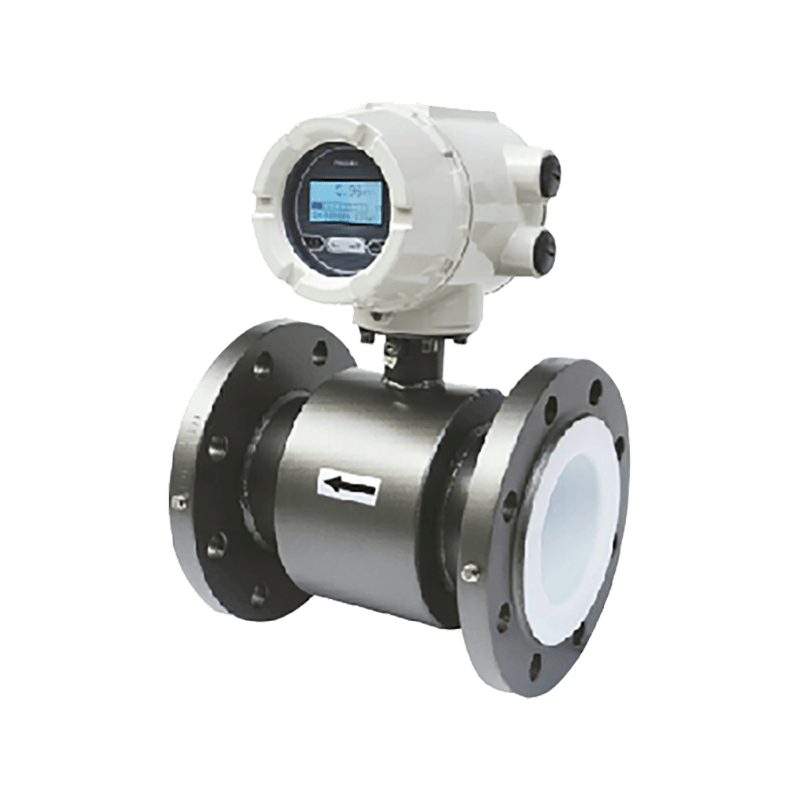 Electromagnetic Water Meter for High-Precision Flow MeasurementA full-bore smart meter with bidirectional measurement, IP68 protection and DN15–DN1200 options, useful for comparing metering technologies before quotation.View Product →
A practical buying checklist should include the following: a water analysis or conductivity range, the minimum and maximum flow, the pipe size and material, the liner and electrode preference, the output and power supply, the enclosure rating, the straight-run availability, the grounding arrangement, and the required documentation. If any of these items is missing, the quotation is not yet a specification. It is only a price.
It also helps to ask how the meter will be verified after installation. A zero check in a full, still pipe is a basic starting point. A simulated output check can confirm the transmitter scaling. A portable clamp-on comparison can provide a second opinion, although it should not be treated as a calibration unless the method and uncertainty are understood. The buying route should make it clear who is responsible for commissioning and who will respond if the reading does not match expectations.
For projects that involve multiple sites, standardizing the transmitter interface and the documentation can reduce long-term training and spare-parts costs. A utility may prefer one output protocol and one enclosure style across a district. An industrial plant may prefer a local display and a simple 4-20 mA signal. These preferences are not technical afterthoughts; they affect how quickly a fault can be diagnosed and how easily a replacement can be installed.
Maintenance and verification in the field
An electromagnetic flowmeter has no moving parts in the flow, but it is not invisible. The electrodes touch the water, the liner insulates the signal, and the transmitter depends on a stable electrical environment. A simple maintenance routine can catch many problems before they become billing disputes or control failures.
The first check is the zero point. With the pipe full and the water still, the meter should read close to zero. If it does not, the cause may be a grounding issue, a damaged liner, a wet terminal box, or a transmitter configuration error. The zero check should be done after installation and then at a sensible interval based on the site conditions. A meter in clean water may need it once a year; a meter in a dirty line may need it more often.
The second check is the electrode condition. In wastewater and slurry lines, the electrodes can become coated with grease, scale, or biological growth. A coating can weaken the signal and cause a slow drift. The maintenance plan should include access to the electrodes and a safe procedure for cleaning them. In some installations, a bypass or a removable sensor section makes this work much easier. In others, the line must be isolated, and the cost of access should be considered at the design stage.
The third check is the liner. A liner that is blistered, cracked, or worn can allow water to reach the electrode seal or the meter body. A visual inspection during a shutdown is more reliable than waiting for a reading to fail. If the liner is damaged, the meter should be repaired or replaced before it is returned to service. A temporary reading that looks plausible is not evidence that the liner is sound.
Verification is easier when the installation includes a way to compare the meter with a second measurement. A portable ultrasonic meter can be used as a cross-check, provided the pipe condition and the flow profile are suitable. A tank-fill test can be used where a known volume can be diverted. A master meter comparison can be useful in a utility network, but the uncertainty of the reference meter should be known. The goal is to detect a meaningful change, not to chase a difference that is within the combined uncertainty of the two methods.
Records matter. A commissioning sheet with the meter tag, serial number, pipe size, flow range, conductivity, liner, electrode, grounding method, and zero-check result will save time when the meter is serviced years later. If the person who installed the meter has left the site, the record is the only reliable description of what was actually built. That is a practical maintenance tool, not paperwork for its own sake.
FAQ about electromagnetic flowmeters
What is the minimum conductivity for an electromagnetic flowmeter?
Many general-purpose electromagnetic flowmeters require a minimum conductivity around 5 µS/cm, but the exact figure depends on the meter design. Low-conductivity versions are available and should be checked against a water analysis. If the liquid is demineralized water or a non-conductive process fluid, a different measurement principle may be more suitable.
Can an electromagnetic flowmeter be installed vertically?
Yes, but the preferred direction is upward flow so the pipe stays full and air can escape. A vertical installation should avoid downward flow where the pipe may partially empty. The manufacturer’s manual should be followed for the specific meter and the available straight run.
Do electromagnetic flowmeters work with wastewater?
They can work well in wastewater when the meter is specified with a suitable liner and electrode material and the pipe runs full. Abrasive sludge, rags, and grease can affect the electrodes or the liner, so the maintenance plan and the installation layout need to account for cleaning and access.
How much straight pipe is needed?
The requirement varies by meter size and upstream disturbance. A common recommendation is several diameters upstream and a few diameters downstream, with more length after a pump, valve, or double bend. The exact figure should come from the manufacturer, but the purpose is always the same: a representative velocity profile at the electrodes.
Why does grounding matter so much?
The flow signal is a small voltage. Without a stable electrical reference, electrical noise from pumps, motors, or nearby cables can distort the reading. Grounding the sensor, pipe, and liquid according to the installation instructions is not optional. In isolated or plastic-lined piping, earthing rings or grounding electrodes may be required.
Can a mag meter measure low flow accurately?
It can, but the meter must be sized so that the low flow is within its usable range. An oversized meter may struggle at the bottom of the range. The datasheet should be checked for the minimum measurable flow and the turndown ratio, and the normal operating flow should sit comfortably inside that range.
How often should a mag meter be calibrated?
There is no single interval that fits every site. Clean water applications may need verification less often than dirty or chemical duties. A practical plan includes a zero check, a signal check, and a comparison with a second method when a reading is questioned. Local regulations or billing requirements may set a formal calibration interval.
What is the difference between an electromagnetic flowmeter and an ultrasonic water meter?
An electromagnetic flowmeter requires a conductive liquid and uses electrodes in contact with the water. An ultrasonic meter uses sound waves and can be clamp-on or in-line. Ultrasonic meters can work with some non-conductive liquids, while mag meters are often chosen for stable full-bore water measurement with low pressure loss. The better choice depends on the liquid, the pipe, and the installation access.
Are electromagnetic flowmeters suitable for drinking water?
Yes, when the liner, electrodes, and approvals are suitable for potable water. Stainless steel electrodes and a food-grade liner are common, but the final selection should follow local water contact requirements. The meter should also be installed so that it can be cleaned and inspected without compromising the water quality.
What should I check before buying from a manufacturer or supplier?
Ask for the conductivity range, the flow range, the pipe size, the liner and electrode options, the output and power supply, the enclosure rating, the straight-run requirement, and the documentation package. A supplier who asks about the application before quoting is usually a better partner than one who quotes on pipe diameter alone.
A practical next step for water meter projects
If a project is moving toward an electromagnetic flowmeter, the next step is to assemble a short technical brief before requesting quotations. The brief should include the pipe size and material, the liquid and its conductivity, the minimum and maximum flow, the normal operating hours, the available straight run, the grounding arrangement, the output and power supply, and the environment at the installation point. A simple sketch of the pipe layout is often more useful than a long description.
From there, the comparison can focus on the details that actually affect service: liner and electrode suitability, pressure loss, verification options, spare parts, and commissioning support. A lower purchase price is not a saving if the meter cannot be grounded properly, if the liner fails in the first year, or if the reading cannot be checked without a shutdown. A higher specification is not automatically better either; it is only better when it matches the duty.
For buyers who need a starting point within a broader product range, it can help to review the water meter product range and compare the electromagnetic option with mechanical, ultrasonic, and wireless alternatives. The right answer may be a mag meter for the main line and a different technology for a small branch. That is not a compromise; it is a properly engineered metering plan.
The most reliable projects treat the meter as part of the hydraulic and electrical system, not as a standalone catalogue item. When the specification, installation, and verification are planned together, an electromagnetic flowmeter can provide a stable measurement for many years with relatively little attention. When they are separated, even a good meter can become a recurring problem.